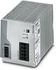
TRIO-PS-2G/3AC – Alimentation triphasée sur rail DIN
Alimentations à découpage pour conversion AC/DC régulée
- Tension de sortie 24V DC
- Courant de sortie : 5, 10, 20 ou 40 A
- Puissance de sortie : 120, 240, 480 ou 960 W
- Plage de tension d’entrée AC triphasée : 400 à 500 V AC
Les alimentations industrielles triphasées TRIO offrent une gamme complète de robustes convertisseurs AC/DC conçus pour répondre aux exigences de stabilité et d’efficacité élevées des environnements industriels, de l’automatisation des machines et du contrôle des processus. Ces alimentations avec mode découpage assurent une tension de sortie régulée même en cas de fluctuations de tension dans le réseau d’alimentation. Grâce à toutes les certifications de sécurité leur permettant de prendre en charge des équipements informatiques (EI), à un conditionnement robuste, à des températures de fonctionnement étendues, à des capacités de pic de charge élevées et à des tensions d’isolation élevées, les alimentations industrielles triphasées TRIO sont conçues pour répondre aux besoins de votre application industrielle.
150 % d’amplification de puissance dynamique

L’amplification dynamique fournit un supplément de puissant pour faciliter le démarrage en cas de charges difficiles. En fournissant jusqu’à 150 % du courant nominal pendant 5 secondes, les alimentations TRIO assurent de façon fiable le démarrage de charges difficiles.
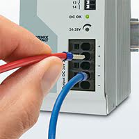
Plage de tension de sortie réglable de 24 à 28 V DC
Grâce au potentiomètre rotatif en façade de l’alimentation TRIO, la tension de sortie peut être réglée et répondre de façon optimale aux exigences d’environnements d’application spécifiques. Par exemple, vous pouvez facilement la régler pour compenser une chute de tension due à une importante longueur de câble.
Température de fonctionnement industriel de -25 °C à +70 °C
Les applications industrielles et en extérieur de ces équipements utilisés pour la gestion de trafic, les pipelines pétroliers et gaziers ou la surveillance météorologique, impliquent un fonctionnement à des températures qui ne peuvent pas être supportées par des alimentations commerciales. Avec une température de fonctionnement de -25 °C à +70 °C, l’alimentation industrielle triphasée TRIO est idéale pour une utilisation avec des équipements soumis à des environnements difficiles et à des températures extrêmes. Certains modèles garantissent même un démarrage fiable des dispositifs à -40 °C.
Consommation électrique à rendement élevé et très économique en l’absence de charge
Par rapport aux autres produits du marché, l’alimentation triphasée TRIO permet d’importantes économies d’énergie. Grâce à une consommation d’énergie très faible en l’absence de charge et à une efficacité élevée à la charge nominale, seule une faible quantité d’énergie électrique est convertie en chaleur non désirée, rendant ces alimentations très écologiques.
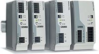
Installation facile et efficace
La connexion enfichable sans outil permet un gain de temps et une installation rapide et facile. La fixation sur rail DIN à boîtier étroit permet un gain de place dans l’armoire de commande.
Environnements d’application parfaits pour une alimentation TRIO sur rail DIN
- moteurs d’entraînement et autres dispositifs
- construction de machines
- processus de production automatisé
- commande, automatisation, assemblage et équipement de test industriels
- systèmes de contrôle de bâtiment, de sécurité et surveillance et de climatisation.
- alimentez de nombreux dispositifs d’automatisation industriels tels que capteurs, contrôleurs et valves
Autres raisons de choisir une alimentation industrielle TRIO
- Sortie de signal de contact et voyant LED en cas de défaut de tension de sortie : Si la tension de sortie est inférieure à la plage de fonctionnement, le voyant LED s’éteint et le contact s’ouvre.
- Résistance aux vibrations jusqu’à 4 kg
- Résistance aux chocs jusqu’à 30 g
- Isolation de tension entrée/sortie : 3 kV AC
- Protections : Court-circuit, surcharge, surtension, surchauffe
- Temps moyen entre pannes (MTBF) élevé, pour une disponibilité maximale
Specifications
HTSUS Number:
TRIO-PS-2G/3AC/24DC/5: 8504.40.7007, TRIO-PS-2G/3AC/24DC/10: 8504.40.7012, TRIO-PS-2G/3AC/24DC/20: 8504.40.7012, TRIO-PS-2G/3AC/24DC/40: 8504.40.7012
UNSPSC Code:
39121004
ECCN:
EAR99

Environmental Product Compliance
REACH SVHC
TRIO-PS-2G/3AC/24DC/5 - 29031538
TRIO-PS-2G/3AC/24DC/10 - 29031548
TRIO-PS-2G/3AC/24DC/20 - 29031558
Lead 7439-92-1
TRIO-PS-2G/3AC/24DC/40 - 29031568
Lead 7439-92-1
China RoHS
Environmentally Friendly Use Period = 25;
General
Net weight
TRIO-PS-2G/3AC/24DC/5 - 29031538
0.4 kg
TRIO-PS-2G/3AC/24DC/10 - 29031548
0.9 kg
TRIO-PS-2G/3AC/24DC/20 - 29031558
1.5 kg
TRIO-PS-2G/3AC/24DC/40 - 29031568
2.6 kg
Efficiency
TRIO-PS-2G/3AC/24DC/5 - 29031538
> 91 % (at 400 V AC and nominal values)
TRIO-PS-2G/3AC/24DC/10 - 29031548
> 92 % (at 400 V AC and nominal values)
TRIO-PS-2G/3AC/24DC/20 - 29031558
> 93 % (400 V AC)
TRIO-PS-2G/3AC/24DC/40 - 29031568
typ. 93 % (400 V AC)
Insulation voltage input/output
- 3 kV AC (type test)
- 1.5 kV AC (routine test)
Protection class
TRIO-PS-2G/3AC/24DC/5 - 29031538
II (in closed control cabinet)
TRIO-PS-2G/3AC/24DC/10 - 29031548
I (in closed control cabinet)
TRIO-PS-2G/3AC/24DC/20 - 29031558
I (in closed control cabinet)
TRIO-PS-2G/3AC/24DC/40 - 29031568
I (in closed control cabinet)
Degree of protection
IP20
MTBF (IEC 61709, SN 29500)
TRIO-PS-2G/3AC/24DC/5 - 29031538
> 2300000 h (25°C)
> 1300000 h (40°C)
> 620000 h (60°C)
TRIO-PS-2G/3AC/24DC/10 - 29031548
> 2100000 h (25°C)
> 1200000 h (40°C)
> 590000 h (60°C)
TRIO-PS-2G/3AC/24DC/20 - 29031558
> 1800000 h (25°C)
> 1100000 h (40°C)
> 510000 h (60°C)
TRIO-PS-2G/3AC/24DC/40 - 29031568
> 1730000 h (25°C)
> 1051000 h (40°C)
> 510000 h (60°C)
Mounting position
horizontal DIN rail NS 35, EN 60715
Assembly instructions
alignable: horizontally 0 mm (≤ 40°C) 10 mm (≤ 70°C), vertically 50 mm
Efficiency
TRIO-PS-2G/3AC/24DC/5 - 29031538
TRIO-PS-2G/3AC/24DC/10 - 29031548
TRIO-PS-2G/3AC/24DC/20 - 29031558
500 V AC
TRIO-PS-2G/3AC/24DC/40 - 29031568
typ. 93.3 % (480 V AC)
Standards and Regulations
Electromagnetic compatibility
Conformance with EMC Directive 2014/30/EU
Noise emission
EN 55011 (EN 55022)
Noise immunity
TRIO-PS-2G/3AC/24DC/5 - 29031538
Immunity according to EN 61000-6-2 (industrial)
TRIO-PS-2G/3AC/24DC/10 - 29031548
Immunity according to EN 61000-6-2 (industrial)
TRIO-PS-2G/3AC/24DC/20 - 29031558
Immunity according to EN 61000-6-2 (industrial)
TRIO-PS-2G/3AC/24DC/40 - 29031568
Immunity according to EN 61000-6-1 (residential), EN 61000-6-2 (industrial)
Standards/regulations
EN 61000-4-2
Contact discharge
4 kV (Test Level 2)
Standards/regulations
EN 61000-4-3
Frequency range
80 MHz ... 1 GHz
Test field strength
10 V/m (Test Level 3)
Frequency range
1.4 GHz ... 2 GHz
Test field strength
3 V/m (Test Level 2)
Standards/regulations
EN 61000-4-4
Comments
Criterion B
Standards/regulations
- EN 61000-6-3
- EN 61000-4-6
Frequency range
0.15 MHz ... 80 MHz
Voltage
10 V (Test Level 3)
Conducted noise emission
EN 55016 EN 61000-6-4 (Class A)
Low Voltage Directive
Conformance with Low Voltage Directive 2014/35/EC
Standard - Safety of transformers
TRIO-PS-2G/3AC/24DC/5 - 29031538
EN 61558-2-16 (air clearances and creepage distances only)
TRIO-PS-2G/3AC/24DC/10 - 29031548
EN 61558-2-16 (air clearances and creepage distances only)
TRIO-PS-2G/3AC/24DC/20 - 29031558
EN 61558-2-16 (air clearances and creepage distances only)
TRIO-PS-2G/3AC/24DC/40 - 29031568
Standard - Electrical safety
IEC 60950-1/VDE 0805 (SELV)
Standard – Electronic equipment for use in electrical power installations and their assembly into electrical power installations
EN 50178/VDE 0160 (PELV)
Standard – Safety extra-low voltage
IEC 60950-1 (SELV) and EN 60204-1 (PELV)
Standard - Safe isolation
DIN VDE 0100-410
Standard – Limitation of mains harmonic currents
EN 61000-3-2
UL approvals
- UL Listed UL 508
- UL/C-UL Recognized UL 60950-1
Shock
TRIO-PS-2G/3AC/24DC/5 - 29031538
18 ms, 30g, in each space direction (according to IEC 60068-2-27)
TRIO-PS-2G/3AC/24DC/10 - 29031548
18 ms, 30g, in each space direction (according to IEC 60068-2-27)
TRIO-PS-2G/3AC/24DC/20 - 29031558
18 ms, 30g, in each space direction (according to IEC 60068-2-27)
TRIO-PS-2G/3AC/24DC/40 - 29031568
11 ms, 15g, in each space direction (according to IEC 60068-2-27)
Vibration (operation)
TRIO-PS-2G/3AC/24DC/5 - 29031538
< 15 Hz, amplitude ±2.5 mm (according to IEC 60068-2-6)
15 Hz ... 150 Hz, 4g, 90 min.
TRIO-PS-2G/3AC/24DC/10 - 29031548
< 15 Hz, amplitude ±2.5 mm (according to IEC 60068-2-6)
15 Hz ... 150 Hz, 4g, 90 min.
TRIO-PS-2G/3AC/24DC/20 - 29031558
< 15 Hz, amplitude ±2.5 mm (according to IEC 60068-2-6)
15 Hz ... 150 Hz, 4g, 90 min.
TRIO-PS-2G/3AC/24DC/40 - 29031568
DNV GL CG-0339 / Class B 2 Hz - 100 Hz resonance search, 90 min. in resonance, 2 Hz - 13.2 Hz, ±1 mm amplitude, 13.2 Hz - 100 Hz, 0.7g acceleration
Rail applications
EN 50121-4
Shipbuilding approval
TRIO-PS-2G/3AC/24DC/5 - 29031538
TRIO-PS-2G/3AC/24DC/10 - 29031548
TRIO-PS-2G/3AC/24DC/20 - 29031558
GL applied for
TRIO-PS-2G/3AC/24DC/40 - 29031568
Standards/regulations
TRIO-PS-2G/3AC/24DC/5 - 29031538
TRIO-PS-2G/3AC/24DC/10 - 29031548
TRIO-PS-2G/3AC/24DC/20 - 29031558
TRIO-PS-2G/3AC/24DC/40 - 29031568
EN 61000-4-11
Overvoltage category (EN 60950-1)
TRIO-PS-2G/3AC/24DC/5 - 29031538
TRIO-PS-2G/3AC/24DC/10 - 29031548
TRIO-PS-2G/3AC/24DC/20 - 29031558
TRIO-PS-2G/3AC/24DC/40 - 29031568
II
Overvoltage category (EN 61010-1)
TRIO-PS-2G/3AC/24DC/5 - 29031538
TRIO-PS-2G/3AC/24DC/10 - 29031548
TRIO-PS-2G/3AC/24DC/20 - 29031558
TRIO-PS-2G/3AC/24DC/40 - 29031568
III
Connection data, input
Connection method
Push-in connection
Conductor cross section solid min.
0.2 mm²
Conductor cross section solid max.
4 mm²
Conductor cross section flexible min.
0.2 mm²
Conductor cross section flexible max.
2.5 mm²
Conductor cross section AWG min.
24
Conductor cross section AWG max.
12
Stripping length
10 mm
Output data
Nominal output voltage
24 V DC ±1 %
Setting range of the output voltage (USet)
24 V DC ... 28 V DC (> 24 V DC, constant capacity restricted)
Nominal output current (IN)
TRIO-PS-2G/3AC/24DC/5 - 29031538
5 A
TRIO-PS-2G/3AC/24DC/10 - 29031548
10 A
TRIO-PS-2G/3AC/24DC/20 - 29031558
20 A
TRIO-PS-2G/3AC/24DC/40 - 29031568
40 A
Dynamic Boost (IDyn.Boost)
TRIO-PS-2G/3AC/24DC/5 - 29031538
7.5 A (5 s)
TRIO-PS-2G/3AC/24DC/10 - 29031548
15 A (5 s)
TRIO-PS-2G/3AC/24DC/20 - 29031558
30 A (5 s)
TRIO-PS-2G/3AC/24DC/40 - 29031568
60 A (5 s)
Derating
60°C ... 70°C (2.5%/K)
Connection in parallel
Yes, for redundancy and increased capacity
Connection in series
Yes
Protection against surge voltage on the output
≤ 30 V DC
Control deviation
- < 1 % (change in load, static 10 % ... 90 %)
- < 3 % (Dynamic load change 10 % ... 90 %, 10 Hz)
- < 0.1 % (change in input voltage ±10 %)
Residual ripple
TRIO-PS-2G/3AC/24DC/5 - 29031538
≤ 20 mVPP
TRIO-PS-2G/3AC/24DC/10 - 29031548
≤ 20 mVPP
TRIO-PS-2G/3AC/24DC/20 - 29031558
≤ 20 mVPP
TRIO-PS-2G/3AC/24DC/40 - 29031568
≤ 50 mVPP
Output power
TRIO-PS-2G/3AC/24DC/5 - 29031538
120 W
TRIO-PS-2G/3AC/24DC/10 - 29031548
240 W
TRIO-PS-2G/3AC/24DC/20 - 29031558
480 W
TRIO-PS-2G/3AC/24DC/40 - 29031568
960 W
Typical response time
< 1 s
Maximum power dissipation in no-load condition
TRIO-PS-2G/3AC/24DC/5 - 29031538
< 1 W (400 V AC)
TRIO-PS-2G/3AC/24DC/10 - 29031548
< 1.1 W (400 V AC)
TRIO-PS-2G/3AC/24DC/20 - 29031558
< 1.2 W (400 V AC)
TRIO-PS-2G/3AC/24DC/40 - 29031568
< 14 W (400 V AC)
Power loss nominal load max.
TRIO-PS-2G/3AC/24DC/5 - 29031538
< 12 W (480 V AC)
TRIO-PS-2G/3AC/24DC/10 - 29031548
< 22 W (480 V AC)
TRIO-PS-2G/3AC/24DC/20 - 29031558
< 38 W (480 V AC)
TRIO-PS-2G/3AC/24DC/40 - 29031568
< 68 W (480 V AC)
Feedback resistance
TRIO-PS-2G/3AC/24DC/5 - 29031538
TRIO-PS-2G/3AC/24DC/10 - 29031548
TRIO-PS-2G/3AC/24DC/20 - 29031558
TRIO-PS-2G/3AC/24DC/40 - 29031568
< 35 V
Short-circuit current
TRIO-PS-2G/3AC/24DC/5 - 29031538
TRIO-PS-2G/3AC/24DC/10 - 29031548
TRIO-PS-2G/3AC/24DC/20 - 29031558
TRIO-PS-2G/3AC/24DC/40 - 29031568
< (Permanent)
Connection data for signaling
Connection method
Push-in connection
Conductor cross section solid min.
0.2 mm²
Conductor cross section solid max.
1.5 mm²
Conductor cross section flexible min.
0.2 mm²
Conductor cross section flexible max.
1.5 mm²
Conductor cross section AWG min.
24
Conductor cross section AWG max.
16
Stripping length
8 mm
Dimensions
Width
TRIO-PS-2G/3AC/24DC/5 - 29031538
35 mm
TRIO-PS-2G/3AC/24DC/10 - 29031548
42 mm
TRIO-PS-2G/3AC/24DC/20 - 29031558
65 mm
TRIO-PS-2G/3AC/24DC/40 - 29031568
110 mm
Height
130 mm
Depth
TRIO-PS-2G/3AC/24DC/5 - 29031538
115 mm
TRIO-PS-2G/3AC/24DC/10 - 29031548
160 mm
TRIO-PS-2G/3AC/24DC/20 - 29031558
160 mm
TRIO-PS-2G/3AC/24DC/40 - 29031568
160 mm
Weight per piece
TRIO-PS-2G/3AC/24DC/5 - 29031538
568.5 GRM
TRIO-PS-2G/3AC/24DC/10 - 29031548
1070.0 GRM
TRIO-PS-2G/3AC/24DC/20 - 29031558
1717.0 GRM
TRIO-PS-2G/3AC/24DC/40 - 29031568
2850.0 GRM
Input data
Nominal input voltage range
TRIO-PS-2G/3AC/24DC/5 - 29031538
- 3x 400 V AC ... 500 V AC
- 2x 400 V AC ... 500 V AC
TRIO-PS-2G/3AC/24DC/10 - 29031548
- 3x 400 V AC ... 500 V AC
- 2x 400 V AC ... 500 V AC
TRIO-PS-2G/3AC/24DC/20 - 29031558
- 3x 400 V AC ... 500 V AC
- 2x 400 V AC ... 500 V AC
TRIO-PS-2G/3AC/24DC/40 - 29031568
- 3x 400 V AC ... 500 V AC
Input voltage range
TRIO-PS-2G/3AC/24DC/5 - 29031538
- 3x 400 V AC ... 500 V AC -20 % ....+15 %
- 2x 400 V AC ... 500 V AC -10 % ... +15 %
TRIO-PS-2G/3AC/24DC/10 - 29031548
- 3x 400 V AC ... 500 V AC -20 % ....+15 %/li>
- 2x 400 V AC ... 500 V AC -10 % ... +15 %
TRIO-PS-2G/3AC/24DC/20 - 29031558
- 3x 400 V AC ... 500 V AC -20 % ....+15 %
- 2x 400 V AC ... 500 V AC -10 % ... +15 %
TRIO-PS-2G/3AC/24DC/40 - 29031568
- 3x 400 V AC ... 500 V AC -20 % ....+15 %
AC frequency range
50 Hz ... 60 Hz
Discharge current to PE
TRIO-PS-2G/3AC/24DC/5 - 29031538
< 0.25 mA
TRIO-PS-2G/3AC/24DC/10 - 29031548
< 3.5 mA
TRIO-PS-2G/3AC/24DC/20 - 29031558
< 3.5 mA
TRIO-PS-2G/3AC/24DC/40 - 29031568
< 3.5 mA
Current consumption
TRIO-PS-2G/3AC/24DC/5 - 29031538
- 3x 0.4 A (400 V AC)
- 3x 0.3 A (500 V AC)
- 2x 0.6 A (400 V AC)
- 2x 0.5 A (500 V AC)
TRIO-PS-2G/3AC/24DC/10 - 29031548
- 3x 0.6 A (400 V AC)
- 3x 0.6 A (500 V AC)
- 2x 1.1 A (400 V AC)
- 2x 1.1 A (500 V AC)
TRIO-PS-2G/3AC/24DC/20 - 29031558
- 3x 1.2 A (400 V AC)
- 3x 1 A (500 V AC)
- 2x 2.3 A (400 V AC)
- 2x 1.9 A (500 V AC)
TRIO-PS-2G/3AC/24DC/40 - 29031568
- 3x 1.9 A (400 V AC)
- 3x 1.9 A (400 V AC)
Nominal power consumption
TRIO-PS-2G/3AC/24DC/5 - 29031538
243.6 VA
TRIO-PS-2G/3AC/24DC/10 - 29031548
451.7 VA
TRIO-PS-2G/3AC/24DC/20 - 29031558
822.2 VA
TRIO-PS-2G/3AC/24DC/40 - 29031568
1335.1 VA
Inrush surge current
TRIO-PS-2G/3AC/24DC/5 - 29031538
≤ 22 A (typical)
TRIO-PS-2G/3AC/24DC/10 - 29031548
≤ 26 A (typical)
TRIO-PS-2G/3AC/24DC/20 - 29031558
≤ 22 A (typical)
TRIO-PS-2G/3AC/24DC/40 - 29031568
≤ (typical)
Mains buffering
TRIO-PS-2G/3AC/24DC/5 - 29031538
- typ. 20 ms (400 V AC)
- typ. 20 ms (500 V AC)
TRIO-PS-2G/3AC/24DC/10 - 29031548
- typ. 10 ms (400 V AC)
- typ. 20 ms (500 V AC)
TRIO-PS-2G/3AC/24DC/20 - 29031558
- typ. 10 ms (400 V AC)
- typ. 20 ms (500 V AC)
TRIO-PS-2G/3AC/24DC/40 - 29031568
- typ. 10 ms (400 V AC)
- typ. 20 ms (500 V AC)
Input fuse
TRIO-PS-2G/3AC/24DC/5 - 29031538
3.15 A (internal (device protection), slow-blow)
TRIO-PS-2G/3AC/24DC/10 - 29031548
3.15 A (internal (device protection), slow-blow)
TRIO-PS-2G/3AC/24DC/20 - 29031558
3.15 A (internal (device protection), slow-blow)
TRIO-PS-2G/3AC/24DC/40 - 29031568
6.3 A (internal (device protection))
Choice of suitable circuit breakers
TRIO-PS-2G/3AC/24DC/5 - 29031538
6 A ... 16 A (Characteristics B, C, D, K)
TRIO-PS-2G/3AC/24DC/10 - 29031548
6 A ... 16 A (Characteristics B, C, D, K)
TRIO-PS-2G/3AC/24DC/20 - 29031558
6 A ... 16 A (Characteristics B, C, D, K)
TRIO-PS-2G/3AC/24DC/40 - 29031568
10 A ... 16 A (Characteristics B, C, D, K)
Power factor (cos phi)
TRIO-PS-2G/3AC/24DC/5 - 29031538
0.55
TRIO-PS-2G/3AC/24DC/10 - 29031548
0.58
TRIO-PS-2G/3AC/24DC/20 - 29031558
0.63
TRIO-PS-2G/3AC/24DC/40 - 29031568
0.77
Type of protection
Transient surge protection
Protective circuit/component
Varistor
Connection data, onput
Connection method
Push-in connection
Conductor cross section solid min.
0.2 mm²
Conductor cross section solid max.
TRIO-PS-2G/3AC/24DC/5 - 29031538
4 mm²
TRIO-PS-2G/3AC/24DC/10 - 29031548
4 mm²
TRIO-PS-2G/3AC/24DC/20 - 29031558
10 mm²
TRIO-PS-2G/3AC/24DC/40 - 29031568
16 mm²
Conductor cross section flexible min.
TRIO-PS-2G/3AC/24DC/5 - 29031538
0.2 mm²
TRIO-PS-2G/3AC/24DC/10 - 29031548
0.2 mm²
TRIO-PS-2G/3AC/24DC/20 - 29031558
0.2 mm²²
TRIO-PS-2G/3AC/24DC/40 - 29031568
0.75 mm²
Conductor cross section flexible max.
TRIO-PS-2G/3AC/24DC/5 - 29031538
2.5 mm²
TRIO-PS-2G/3AC/24DC/10 - 29031548
2.5 mm²
TRIO-PS-2G/3AC/24DC/20 - 29031558
6 mm²
TRIO-PS-2G/3AC/24DC/40 - 29031568
10 mm²
Conductor cross section AWG min.
TRIO-PS-2G/3AC/24DC/5 - 29031538
24
TRIO-PS-2G/3AC/24DC/10 - 29031548
24
TRIO-PS-2G/3AC/24DC/20 - 29031558
24
TRIO-PS-2G/3AC/24DC/40 - 29031568
20
Conductor cross section AWG max.
TRIO-PS-2G/3AC/24DC/5 - 29031538
12
TRIO-PS-2G/3AC/24DC/10 - 29031548
12
TRIO-PS-2G/3AC/24DC/40 - 29031568
8
TRIO-PS-2G/3AC/24DC/20 - 29031558
4
Stripping length
TRIO-PS-2G/3AC/24DC/5 - 29031538
10 mm
TRIO-PS-2G/3AC/24DC/10 - 29031548
10 mm
TRIO-PS-2G/3AC/24DC/20 - 29031558
15 mm
TRIO-PS-2G/3AC/24DC/40 - 29031568
18 mm
Ambient conditions
Degree of protection
IP20
Ambient temperature (operation)
25°C ... 70°C (> 60°C Derating: 2.5 %/K)
Ambient temperature (storage/transport)
-40°C ... 85°C
Max. permissible relative humidity (operation)
≤ 95 % (at 25°C, non-condensing)
Climatic class
3K3 (in acc. with EN 60721)
Degree of pollution
2
Installation height
TRIO-PS-2G/3AC/24DC/5 - 29031538
≤ 5000 m (> 2000 m, Derating: 10 %/1000 m)
TRIO-PS-2G/3AC/24DC/10 - 29031548
≤ 5000 m (> 2000 m, Derating: 10 %/1000 m)
TRIO-PS-2G/3AC/24DC/20 - 29031558
≤ 5000 m (> 2000 m, Derating: 10 %/1000 m)
TRIO-PS-2G/3AC/24DC/40 - 29031568
≤ 4000 m (> 2000 m, Derating: 10 %/1000 m)
Ambient temperature (start-up type tested)
TRIO-PS-2G/3AC/24DC/5 - 29031538
TRIO-PS-2G/3AC/24DC/10 - 29031548
-40°C
TRIO-PS-2G/3AC/24DC/20 - 29031558
-40°C
TRIO-PS-2G/3AC/24DC/40 - 29031568
-40°C
Approvals
- DNV GL
- cULus Listed
- cULus Recognized
- EAC
- UL Recognized
- cUL Recognized
- cUL Listed
- IECEE CB Scheme
- UL Listed
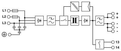
Application Diagrams
TRIO 3-Phase Power Supplies Schéma de Bloc d'arrivée d'alimentation Industriel
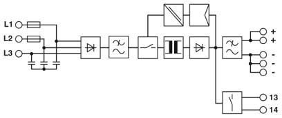
TRIO 3-Phase Power Supplies Schéma de Bloc d'arrivée d'alimentation Industriel
Fare cliquez sur le numéro de la partie du produit pour obtenir des informations sur la commande.
Image du produit
La description
Numéro d’article
TRIO-PS-2G/3AC/24DC/5 Power Supply - TRIO power supply with push-in connection for DIN rail mounting, input: 3-phase, output: 24 V DC/5 A
TRIO-PS-2G/3AC/24DC/10 Power Supply - TRIO power supply with push-in connection for DIN rail mounting, input: 3-phase, output: 24 V DC/10 A
TRIO-PS-2G/3AC/24DC/20 Power Supply - TRIO power supply with push-in connection for DIN rail mounting, input: 3-phase, output: 24 V DC/20 A
TRIO-PS-2G/3AC/24DC/40 Power Supply - TRIO supply for DIN rail mounting, input: 3-phase, output: 24 V DC/40 A